Universal Serial Bus
Three speeds:
- High (480 Mbits/s)
- Full (12)
- Low (1.5)
and then USB 3 came along..
USB is HOST controlled. Only one HOST per bus (bunch of connections). On-The-Go was then tacked on.. but don’t worry too much.
USB addresses allow for 127 ‘slave’ devices. Hubs can be involved, but maximum number of tiers is 6 (root hub included). Limitation of cable is 5 metres.
Star Topology - every device is connected to a “root”. Benefits was that each sub could switch a device if it draws too much current, high speed doesn’t overload low speed… etc. Better than daisy chaining.
The S in USB is serial - data is sent one bit at a time over a wire (or pairs). Two power wires (+5V, GND) and two twisted pair differential data signals (D+, D-). Something about NRZI, but I’m not an electrical engineer.
The B in USB is bus - a way of data transmission.
USB is hot-pluggable. When new device is inserted, the host interrogates it and loads the driver.
Supports Control, Interrupt, Bulk and Isochronous transfers. Each transfer mode provides the designer trade-offs in areas such as error detection and recovery, guaranteed latency and bandwidth.
Isochronous allows a device to reserve a defined amount of bandwidth with guaranteed latency
Electricals
Data
J and K states are weird, they are different depending on speed.
USB uses NRZI (Non-Return-to-Zero Inverted) encoding:
1 → no transition
0 → transition (J ↔ K)
Bit stuffing is used to avoid long runs of 1s (so clock recovery keeps working).
SE0 is both lines low (<0.3V)
USB devices work by pulling the D+ or D- to 3.3v (1.5K). Full speed pulls D+, low speed pulls D-.
The receiver defines a differential ‘1’ as D+ 200mV greater than D- and a differential ‘0’ as D+ 200mV less than D-. The polarity of the signal is inverted depending on the speed of the bus. Therefore the terms ‘J’ and ‘K’ states are used in signifying the logic levels. In low speed a ‘J’ state is a differential 0. In high speed a ‘J’ state is a differential 1.
Remember - J is the “idle state”
Power
Devices obtain power from the V_Bus. It specifies its power consumption in 2mA units. Three classes of USB functions:
- low-power bus powered functions: up to 100mA
- high-power: cannot draw more than one unit load (100mA) unless it is configured, then can draw 5
- self powered: cannot draw more than one unit load, must have provisions in place
Suspend
Now, suspend mode is MANDATORY on all devices. It essentially turns 1 unit load into 500uA. When no activity on bus for > 3.0ms, it has 7.0ms to shut down.
To prevent random suspends:
- A high speed bus will have micro-frames sent every 125.0 µs ±62.5 ns.
- A full speed bus will have a frame sent down each 1.000 ms ±500 ns.
- A low speed bus will have a keep alive which is a EOP (End of Packet) every 1ms only in the absence of any low speed data.
There are also selective suspends. Remote wakeup can also signal host to resume from suspend
Clocks
- High speed data is clocked at 480.00Mb/s with a data signalling tolerance of ± 500ppm.
- Full speed data is clocked at 12.000Mb/s with a data signalling tolerance of ±0.25% or 2,500ppm.
- Low speed data is clocked at 1.50Mb/s with a data signalling tolerance of ±1.5% or 15,000ppm.
Packet Transfer
USB is master-slave. Host initiates all read / write requests.
Little endian - LSBit first.
USB Packet Terms:
- Sync - 8 bits or 32 bits for high speed and is meant to synchronize the clock
- PID - Packet ID. Complemented (bitwise NOT) and repeated to make 8 bits
- ADDR - 7 bits. Address 0 is the special address for “device not yet assigned address”
- ENDP - 4 bits. For endpoints
- CRC - 5 bits. Data packets have 16. Cyclic Redundancy Checks
- EOP - 2 bit times followed by a J for 1 bit time. (K and J states just have to do with the signals, SE0 is both lines LOW)
Packet Types
| Group | PID Value | Packet Identifier |
|---|---|---|
| Token | 0001 | OUT Token |
| Token | 1001 | IN Token |
| Token | 0101 | SOF Token |
| Token | 1101 | SETUP Token |
| Data | 0011 | DATA0 |
| Data | 1011 | DATA1 |
| Data | 0111 | DATA2 |
| Data | 1111 | MDATA |
| Handshake | 0010 | ACK Handshake |
| Handshake | 1010 | NAK Handshake |
| Handshake | 1110 | STALL Handshake |
| Handshake | 0110 | NYET (No Response Yet) |
| Special | 1100 | PREamble |
| Special | 1100 | ERR |
| Special | 1000 | Split |
| Special | 0100 | Ping |
Token
For token packets, the three types are:
- In: USB device that host wants to read info
- Out: Host wants to send USB device info
- Setup: Control transfers
Follows Sync => PID => ADDR => ENDP => CRC5 => EOP
Data
For data packets, there are two types capable of 1024 bytes
- Data0
- Data1
High speed has - Data2
- MDATA
Follows Sync => PID => Data => CRC16 => EOP - Maximum data payload size for low-speed devices is 8 bytes.
- Maximum data payload size for full-speed devices is 1023 bytes.
- Maximum data payload size for high-speed devices is 1024 bytes.
Handshake Packets
Only got the PID.
- ACK: acknowledge package received
- NAK: device temporarily cannot send or receive data. Used during interrupt transactions
- STALL: device needs intervention
Follows Sync => PID => EOP
Start of Frame
The SOF packet consisting of an 11-bit frame number is sent by the host every 1ms ± 500ns on a full speed bus or every 125 µs ± 0.0625 µs on a high speed bus.
Endpoints
Endpoints are sources or sinks. Software may write to the EP1 for example. EP1 OUt is “sink” for host => device. EP1 IN is “source”.
All devices must have endpoint zero. Which is for control / status / enumeration.
Pipes
Client software sends data thru pipes. Pipes = connection from host => endpoint(s). Can be one of the 4 Transfer Types. This means that different endpoints can be used for different types of transfers (gaming headset that needs isochronous for audio, interrupt for vol up/down/mute, control for USB stuff)
Two types:
- Stream pipes: Send any type of data. Predefined in/out. For bulk, isochronous, interrupt. Controlled by host or device (meaning host / device can “control: by filling/emptying buffer)
- Message pipes. Host controlled. In AND out. Only control transfers
Transfer Types
Control Transfers
Command and status operations. “Paperwork”. Uses best effort delivery.
Up to 3 stages:
- The Setup Stage: request is sent. Uses the SETUP Token
- Optional Data Stage. Further divided to IN and OUT Transfers
- IN: Function ignores if malformed. If correct, respond either with DATA or NAK
- Out: Device replies ACK on success, NAK if EP is not empty due to processing previous (Hold on, im still processing!). STALL on error
- Status Stage reports the status of the overall request and this once again varies due to direction of transfer. Status reporting is always performed by the function.
- IN: If the host sent INs, then host must acknowledge with an OUT + zero length data (ZLP). If error, STALL, if busy, NAK
- OUT: If the host sent OUT tokens, the function will acknowledge with a ZLP. If error, STALL, if busy, NAK
Interrupt Transfers
USB devices must wait until host polls to interrupt! Guarantees latency, and error detection.
- IN: Host will periodically poll, configured by endpoint descriptor
- OUT: Send device interrupt data
Isochronous Transfers
Isochronous guarantees a latency bound, and does NOT guarantee message delivery. For things like audio data, where you need guaranteed latency and dropped packets are fine.
Maximum payload size can be configured, high & full speed ONLY.
Usually provides alternatives, lower bandwidth fallback endpoints
Bulk Transfers
For large, bursty transfers. Guarantees DELIVERY of data. Full & high speed modes only.
- IN: Ready to receive data
- OUT: Send data
A Note About Bandwidth
The HOST is responsible for bandwidth management. Usually a percentage is reserved for control transfers.
USB Descriptors
Heart of USB software.
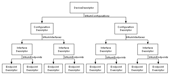
USB
| Offset | Field | Size | Value | Description |
| ------ | ---------------- | ---- | -------- | ---------------------------------- |
| 0 | bLength | 1 | Number | Size of Descriptor in Bytes |
| 1 | bDescriptionType | 1 | Constant | DescriptorType |
| 2 | … | n | | Start of parameters for descriptor |
| | | | | |
Device Descriptors
Defines Product ID / Vendor ID to load specific drivers, USB version, maximum packet size, etc. Also has # of config descriptors
Device Descriptor Format
| Offset | Field | Size | Value | Description |
| ------ | ------------------ | ---- | -------- | --------------------------------------------------------------------------------------------------------------------------------------------------------------------------------------------------------------- |
| 0 | bLength | 1 | Number | Size of the Descriptor in Bytes (18 bytes) |
| 1 | bDescriptorType | 1 | Constant | Device Descriptor (0x01) |
| 2 | bcdUSB | 2 | BCD | USB Specification Number which device complies too. |
| 4 | bDeviceClass | 1 | Class | Class Code (Assigned by USB Org)
If equal to Zero, each interface specifies it’s own class code
If equal to 0xFF, the class code is vendor specified.
Otherwise field is valid Class Code. |
| 5 | bDeviceSubClass | 1 | SubClass | Subclass Code (Assigned by USB Org) |
| 6 | bDeviceProtocol | 1 | Protocol | Protocol Code (Assigned by USB Org) |
| 7 | bMaxPacketSize | 1 | Number | Maximum Packet Size for Zero Endpoint. Valid Sizes are 8, 16, 32, 64 |
| 8 | idVendor | 2 | ID | Vendor ID (Assigned by USB Org) |
| 10 | idProduct | 2 | ID | Product ID (Assigned by Manufacturer) |
| 12 | bcdDevice | 2 | BCD | Device Release Number |
| 14 | iManufacturer | 1 | Index | Index of Manufacturer String Descriptor |
| 15 | iProduct | 1 | Index | Index of Product String Descriptor |
| 16 | iSerialNumber | 1 | Index | Index of Serial Number String Descriptor |
| 17 | bNumConfigurations | 1 | Integer | Number of Possible Configurations |
Configuration Descriptors
Rare. Mutually exclusive, only one configuration allowed at a time. Used for driverlss / drivered scenarios? Host will send a SetConfiguration command to select.
Configuration Descriptor Format
| Offset | Field | Size | Value | Description |
| ------ | ------------------- | ---- | -------- | ---------------------------------------------------------------------------------------------------------------------------- |
| 0 | bLength | 1 | Number | Size of Descriptor in Bytes |
| 1 | bDescriptorType | 1 | Constant | Configuration Descriptor (0x02) |
| 2 | wTotalLength | 2 | Number | Total length in bytes of data returned |
| 4 | bNumInterfaces | 1 | Number | Number of Interfaces |
| 5 | bConfigurationValue | 1 | Number | Value to use as an argument to select this configuration |
| 6 | iConfiguration | 1 | Index | Index of String Descriptor describing this configuration |
| 7 | bmAttributes | 1 | Bitmap | D7 Reserved, set to 1. (USB 1.0 Bus Powered)
D6 Self Powered
D5 Remote Wakeup
D4..0 Reserved, set to 0. |
| 8 | bMaxPower | 1 | mA | Maximum Power Consumption in 2mA units |
Interface Descriptors
These define logical “functions” - multiple can co-exist. Defines a bInterfaceNumber and bAlternative number. bInterface number defines which interface it is, bAlternative defines what alternative it is.
So for example, you can have (0, 0), (1, 0) and (1,1). (1, 0) and (1, 1) are alternatives.
Interface Descriptor Format
| Offset | Field | Size | Value | Description |
| ------ | ------------------ | ---- | -------- | ---------------------------------------------------- |
| 0 | bLength | 1 | Number | Size of Descriptor in Bytes (9 Bytes) |
| 1 | bDescriptorType | 1 | Constant | Interface Descriptor (0x04) |
| 2 | bInterfaceNumber | 1 | Number | Number of Interface |
| 3 | bAlternateSetting | 1 | Number | Value used to select alternative setting |
| 4 | bNumEndpoints | 1 | Number | Number of Endpoints used for this interface. Excludes EP0 |
| 5 | bInterfaceClass | 1 | Class | Class Code (Assigned by USB Org) |
| 6 | bInterfaceSubClass | 1 | SubClass | Subclass Code (Assigned by USB Org) |
| 7 | bInterfaceProtocol | 1 | Protocol | Protocol Code (Assigned by USB Org) |
| 8 | iInterface | 1 | Index | Index of String Descriptor Describing this interface |
Endpoint Descriptors
EP0 is special, it is assumed to be configured. All EP descriptors describe non-zero
Endpoint Descriptors
| Offset | Field | Size | Value | Description |
| ------ | ---------------- | ---- | -------- | --------------------------------------------------------------------------------------------------------------------------------------------------------------------------------------------------------------------------------------------------------------------------------------------------------------------------------------------------------------------------------------------------------------------------------------------------------------------------- |
| 0 | bLength | 1 | Number | Size of Descriptor in Bytes (7 bytes) |
| 1 | bDescriptorType | 1 | Constant | Endpoint Descriptor (0x05) |
| 2 | bEndpointAddress | 1 | Endpoint | Endpoint Address
Bits 0..3b Endpoint Number.
Bits 4..6b Reserved. Set to Zero
Bits 7 Direction 0 = Out, 1 = In (Ignored for Control Endpoints) |
| 3 | bmAttributes | 1 | Bitmap | Bits 0..1 Transfer Type
00 = Control
01 = Isochronous
10 = Bulk
11 = Interrupt
Bits 2..7 are reserved. If Isochronous endpoint,
Bits 3..2 = Synchronisation Type (Iso Mode)
00 = No Synchonisation
01 = Asynchronous
10 = Adaptive
11 = Synchronous
Bits 5..4 = Usage Type (Iso Mode)
00 = Data Endpoint
01 = Feedback Endpoint
10 = Explicit Feedback Data Endpoint
11 = Reserved |
| 4 | wMaxPacketSize | 2 | Number | Maximum Packet Size this endpoint is capable of sending or receiving |
| 6 | bInterval | 1 | Number | Interval for polling endpoint data transfers. Value in frame counts. Ignored for Bulk & Control Endpoints. Isochronous must equal 1 and field may range from 1 to 255 for interrupt endpoints. |
String Descriptors
Optional, if there’s none, then the string descriptors should point to index 0. Index 0 should be a list of languages?
There’s a format for language codes, and the Get Descriptor request can request that language code.
Weird Naming Convention
b - byte
w - word (2 bytes)
dw - (4 bytes)
i - index
bm - bitmap
On-The-Go
Can act as host or device - used in your phone.
Terminology
- Function: A specific logical unit of the device (Audio function for camera, video function for camera)